Integrated Core Drilling Rig
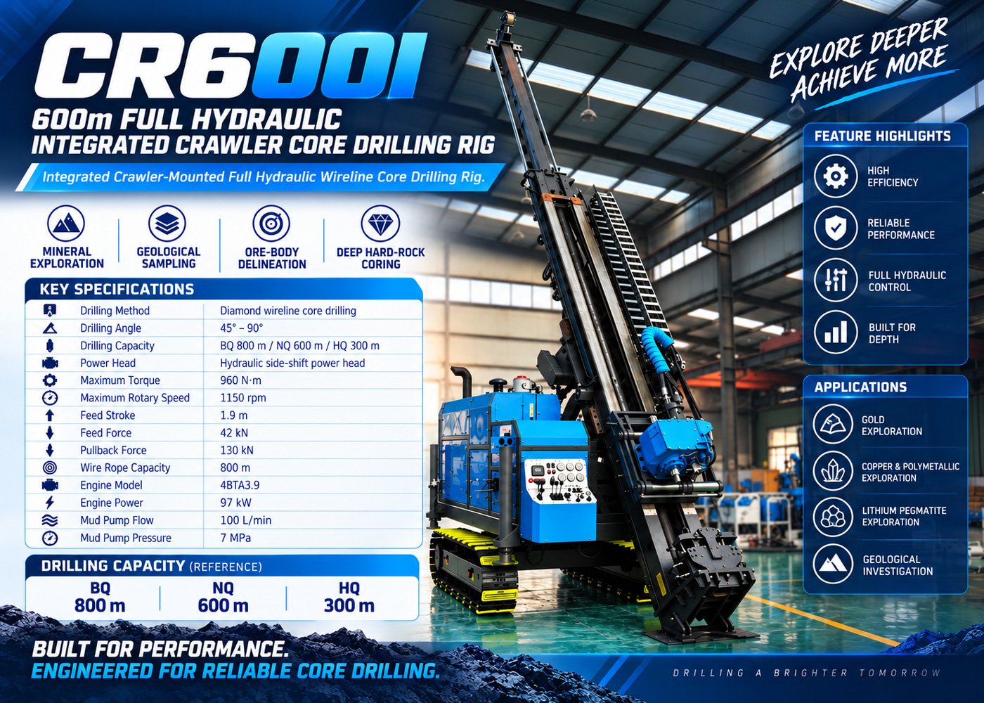
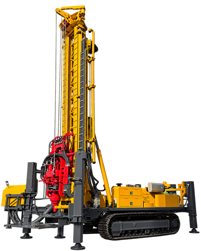
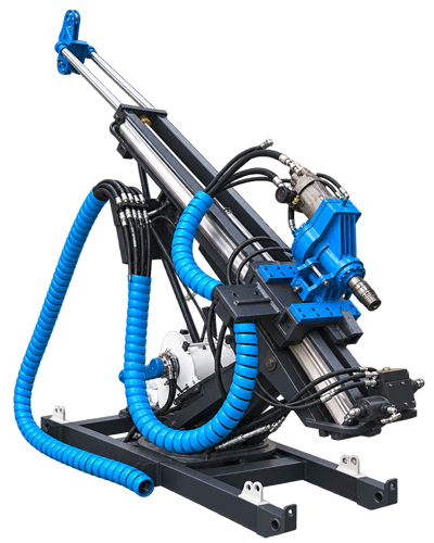
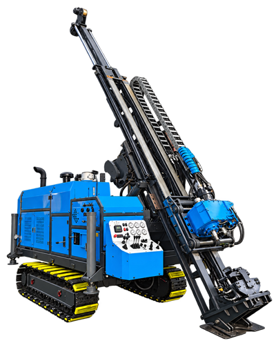
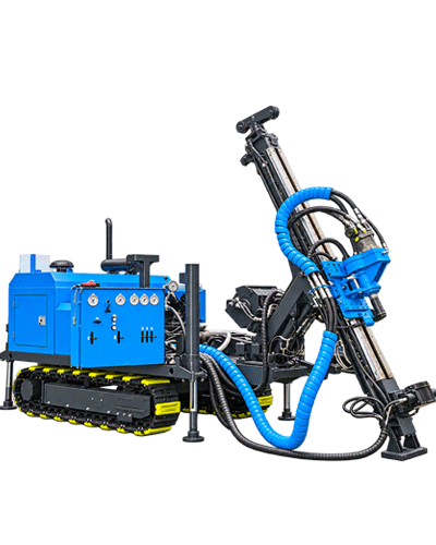
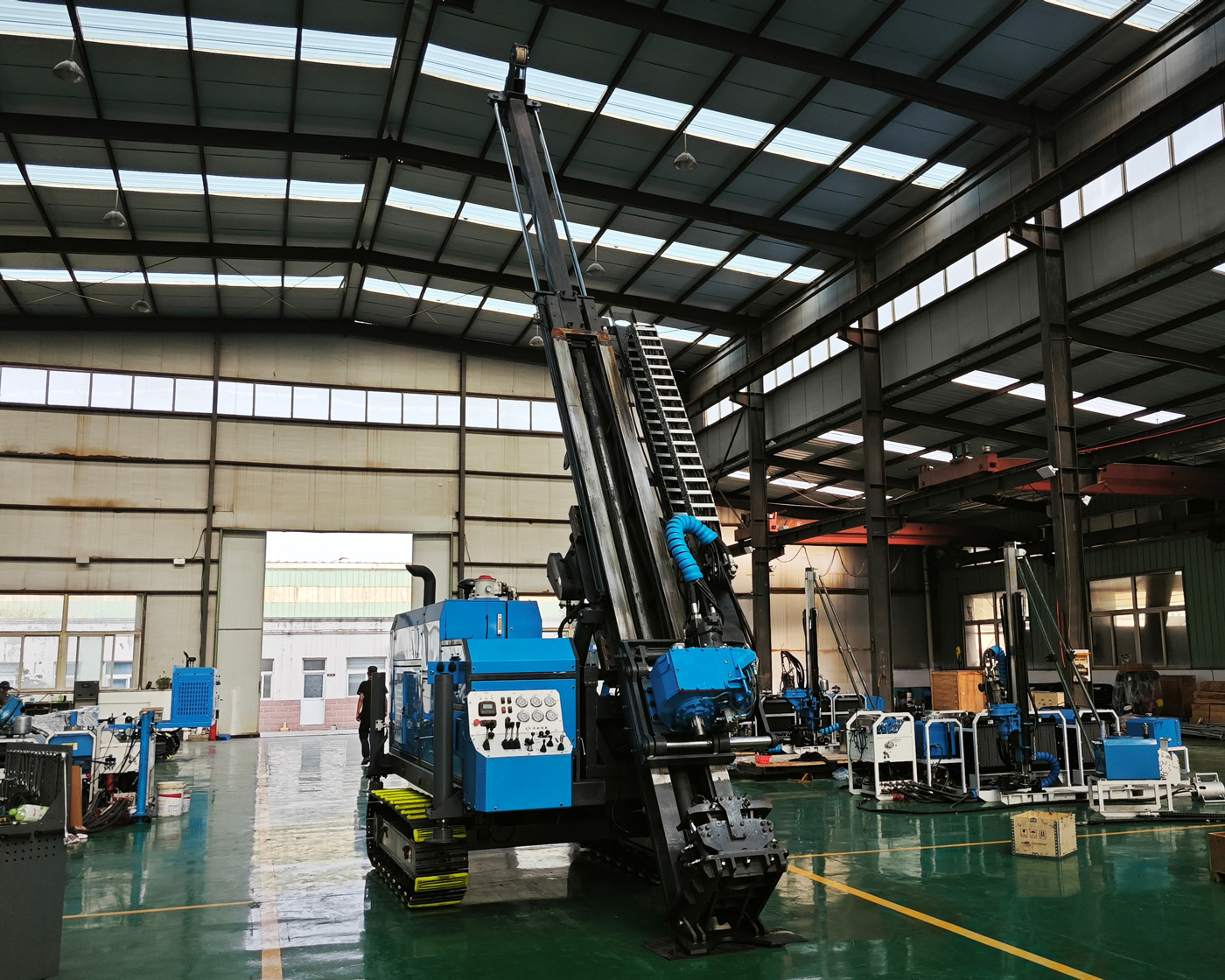
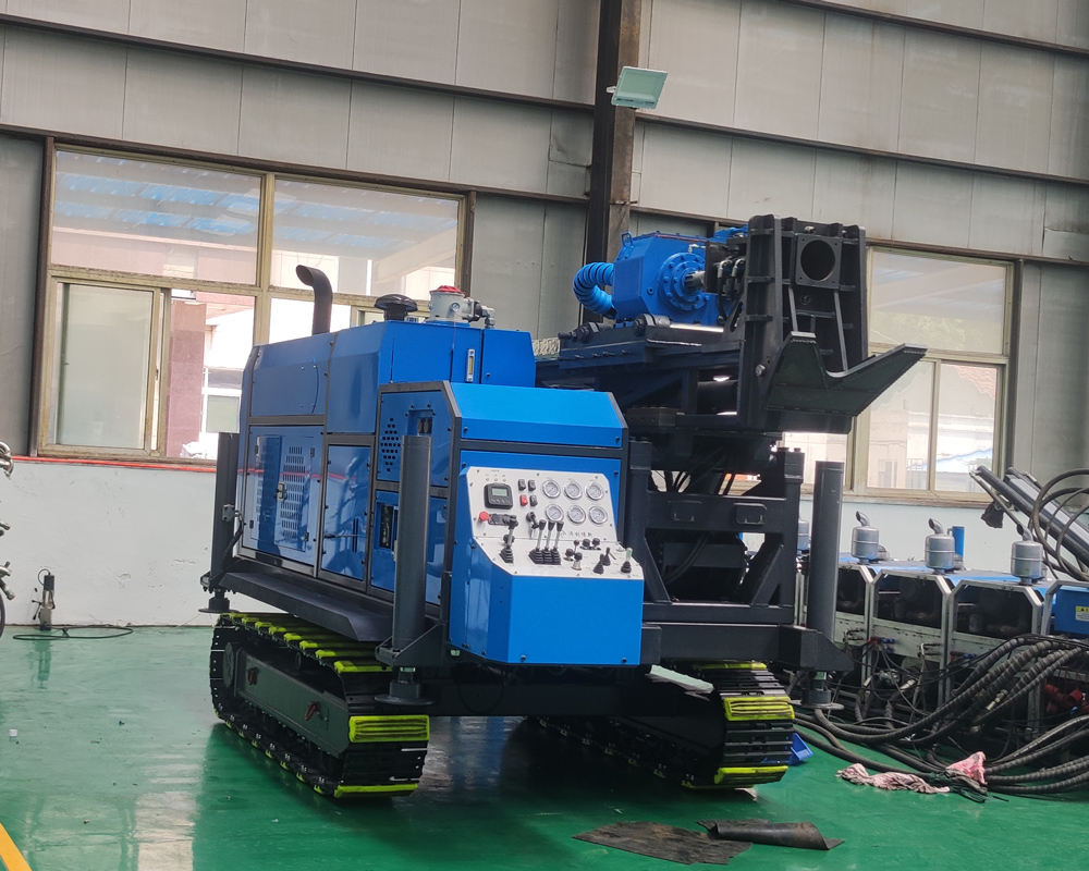
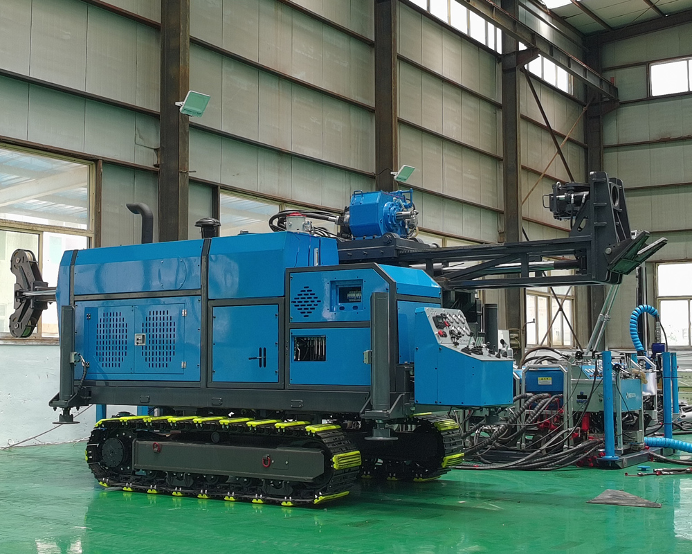
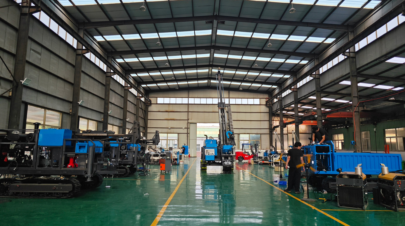
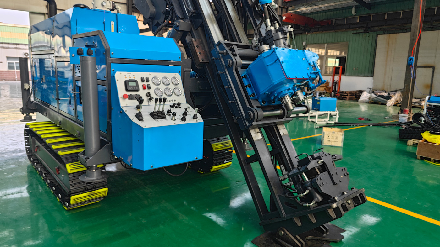
The CR600I is a fully hydraulic integrated crawler core drill rig designed for medium-deep surface core drilling operations. The equipment integrates the power system, hydraulic system, power head, mast and feed mechanism, rod holder, wireline winch, mud circulation system, and crawler travel mechanism on a single platform, reducing the workload of on-site assembly and repeated connections required by split-type equipment. It is more suitable for exploration projects in mining areas, mountainous regions, hills, forest roads, and sites requiring frequent relocation.
This model is positioned with a reference drilling depth of 600 m in N-size, while also accommodating core drilling needs of 800 m in B-size and 300 m in H-size. The drilling angle supports 45°-90°, enabling vertical and inclined holes, suitable for surface exploration, resource evaluation, ore body boundary verification, and deep extension drilling of gold, copper, lithium, iron, lead-zinc, nickel, and other metallic and non-metallic mineral deposits.
CR stands for core drill rig, 600 represents the reference drilling depth of 600 m in N-size, and I indicates the integrated structure. Compared with portable or large split-type core drill rigs, the CR600I emphasizes overall integration, crawler mobility, and rapid on-site deployment. Compared with larger-depth integrated rigs, the 600-meter class is more suitable for medium-depth, multi-hole, continuous surface exploration projects in terms of transportation, operation organization, and equipment investment.
According to typical operating condition reference values in the documentation, the CR600I has drilling capabilities of 800 m in B-size, 600 m in N-size, and 300 m in H-size. Different sizes correspond to different drill rods and core recovery systems. The actual achievable drilling depth is not fixed and is influenced by factors such as drilling angle, rock mass integrity, drill rod weight, downhole tools, mud properties, borehole wall stability, and operating methods.
The CR600I supports drilling within a 45°-90° range, allowing selection of vertical or inclined holes based on ore body occurrence, structural direction, and exploration line layout. For inclined ore bodies, vein-type deposits, fault structures, alteration zones, and concealed ore bodies, selecting an appropriate hole inclination can improve the probability of intersecting the target, avoiding drilling directions too parallel to the ore body strike that would reduce effective ore intersection length.
The power head uses a direct-drive/gear transmission combination, with a maximum torque of 960 N·m, a maximum speed of 1150 rpm, gear shift between direct drive and 1:2.4, and supports hydraulic side shift. The higher speed is suitable for diamond core drilling. By properly matching the drill bit, rotation speed, feed force, and mud parameters, both drilling efficiency and core quality can be achieved. After side-shifting the power head, more convenient working space is provided for drill rod assembly/disassembly, borehole operations, core tool handling, and maintenance.
The mast adopts a folding structure with a feed stroke of 1.9 m, capable of handling 1.5 m drill rods. The feed speed supports fast and slow adjustment, with a feed force of 42 kN and a retraction force of 130 kN. The folding mast helps reduce the transport height and relocation difficulty, while ensuring drilling stability, making it suitable for continuous medium-depth surface core drilling projects.
The wireline winch system uses a 6 mm wire rope with a rope capacity of 800 m, a lifting force of 11 kN, and a lifting speed of 98 m/min. Wireline core recovery allows retrieving the inner tube and core without frequently lifting the entire drill rod string, thereby reducing auxiliary time, especially suitable for continuous medium-deep core drilling operations. For 600 m N-size boreholes, reasonable winch speed and rope capacity help improve per-shift operational efficiency.
The rod holder has a through-hole diameter of 127 mm, compatible with common drill rod systems such as NQ, HQ, PQ, NTW, and HTW. The clamping method uses hydraulic clamping combined with a wedge-shaped self-locking anti-slip structure, providing stable clamping during drill rod connection, disconnection, adding rods, removing rods, and borehole operations, helping to reduce the risk of accidental drill rod slippage and misoperation.
The main pump has a reference flow rate of 220 L/min and a pressure of 20 MPa; the auxiliary pump has a reference flow rate of 60 L/min and a pressure of 17 MPa, with air cooling. The high-flow hydraulic system provides power for the power head, feed, mast, travel, and auxiliary mechanisms. The equipment is also equipped with high-pressure filtration to reduce wear on hydraulic pumps, control valves, and actuators caused by contaminants in the hydraulic oil.
The mud system has a reference flow rate of 100 L/min, pressure of 7 MPa, speed of 360 rpm, and power of 14 kW. Mud circulation in core drilling serves to cool the drill bit, carry rock cuttings, stabilize the borehole wall, lubricate the drilling tools, and improve the downhole environment. When entering fractured zones, highly weathered layers, fissure zones, or loss zones, the mud viscosity, flow rate, and wall protection measures should be adjusted promptly based on return conditions.
The power system uses a 4BTA3.9 model 3.9 L four-cylinder turbocharged direct-injection diesel engine with a rated power of 97 kW, rated speed of 2200 rpm, water cooling, and a 24 V electrical system. This power configuration meets the needs of the power head, hydraulic system, crawler travel, and mud system working together, suitable for continuous field operations and medium-deep core drilling under complex conditions.
The crawler chassis features strong stability, high traction, good off-road capability, and better adaptability to soft ground, suitable for mining access roads, mountainous terrain, hills, gravel roads, mud surfaces, and exploration scenarios requiring frequent hole relocation. The integrated structure reduces the lifting and repeated connection work of split-type equipment, especially suitable for continuous drilling of multiple boreholes within a mining area.
The machine can be equipped with wireless remote control, enabling human-machine separation for some operations within a certain distance. Equipment movement, posture adjustment, and some auxiliary actions can be completed via remote control, reducing the time personnel spend near moving parts such as the crawler, mast, and power head. Wireless remote control does not replace on-site safety management; warning zones should still be set, unified command maintained, and confirmation that no one is near the equipment before operation.
The CR600I is suitable for gold deposit reconnaissance, detailed exploration, infill drilling, and verification of quartz veins, alteration zones, and concealed ore bodies. Through continuous core, it is possible to observe mineralization zone thickness, fracture development, alteration characteristics, wall rock contact relationships, and deep extension, providing basic data for sampling, assay analysis, and 3D geological modeling.
In copper, lead-zinc, nickel, and polymetallic projects, the CR600I can be used for ore body boundary control, structural verification, deep extension assessment, and resource upgrade. Continuous core preserves lithological contacts, mineralization structures, and alteration information relatively completely, facilitating geological personnel in logging, description, and sampling.
For lithium, pegmatite, and other rare metal exploration projects, continuous core can be obtained through a combination of vertical and inclined holes to determine pegmatite body thickness, occurrence, extension direction, mineral assemblage, and grade variation. For mountainous pegmatite mining areas with significant terrain undulation, the crawler integrated structure facilitates relocation between multiple platforms.
The CR600I can also be used for geological surveys and resource verification of iron ore, graphite, phosphate, limestone, and other metallic and non-metallic minerals. For projects requiring continuous stratigraphic data, observation of layer changes, and assessment of rock mass structure, core drilling provides more complete geological information than methods that only obtain cuttings.
In addition to mineral exploration, this model is suitable for regional geological surveys, stratigraphic verification, structural research, supplementary engineering geological drilling, peripheral prospecting in mining areas, and verification of deep extensions of known ore bodies. Through geological logging, RQD statistics, structural surface observation, and laboratory testing of core, data support can be provided for resource evaluation and engineering decisions.
The integrated crawler structure is suitable for construction in mountainous, hilly, forest road, and remote mining areas. Before construction, the transport road width, slope, curve radius, bridge and culvert bearing capacity, platform size, ground bearing capacity, and drainage conditions should be carefully evaluated. For slope operations, the platform should be leveled first and reliable supports set; stability cannot rely solely on friction between the crawler and the ground.
In hard and intact rock formations such as granite, basalt, and quartzite, appropriate diamond bits, matrix hardness, rotation speed, feed force, and mud parameters should be selected based on rock abrasiveness and integrity. Excessive feed force increases bit wear and the risk of hole deviation, while too low feed force may reduce drilling efficiency. Therefore, dynamic adjustment should be made based on weight on bit, pump pressure, and cuttings return.
When entering fault fracture zones, highly fractured zones, or formations with poor core integrity, the feed speed and rotation speed should be appropriately reduced, the length of each core run shortened, and mud wall protection strengthened. If necessary, casing, lost circulation materials, or other borehole wall stabilization measures can be used to reduce hole collapse, sticking, loss, and core loss.
Surface soil, sand-gravel layers, clay layers, and highly weathered rock typically have poor borehole wall stability. Priority should be given to protecting the collar section and casing. After entering stable bedrock, normal core drilling parameters can be gradually adjusted based on rock hardness and integrity. The quality of overburden treatment directly affects the verticality and borehole wall stability of subsequent deep drilling.
When encountering fracture water, strong aquifers, or loss zones, the return flow, pump pressure, downhole fluid level, and mud consumption changes should be promptly observed. Minor losses can be improved by adjusting mud properties; severe losses may require plugging, casing, or staged treatment. Continuing aggressive drilling without treatment can cause insufficient hole cleaning, sticking, or abnormal tool wear.
The core of core drilling is not only drilling deep but also ensuring core quality. During construction, appropriate bits, inner tubes, and core barrels should be selected based on formation conditions, and the length of each run should be reasonably controlled. After core is removed from the barrel, it should be laid out, numbered, photographed, and recorded promptly in depth order to avoid mixing, misordering, or sample contamination.
Actual efficiency depends on bit-formation matching, weight on bit, rotation speed, mud flow rate, hole cleaning, drill rod connection efficiency, and operator experience. Equipment parameters are only basic conditions and cannot alone represent on-site productivity. For continuous projects, bit spare parts, wear parts inventory, mud materials, and routine maintenance plans also directly affect monthly effective footage.
When selecting drilling tools, first confirm the target depth, B/N/H size, drilling angle, main lithology, overburden thickness, and expected fracture zone locations, then determine drill rods, bits, reamers, core barrels, casing, and mud plans. If the project involves special conditions such as high altitude, extreme cold, high temperature, long-distance transport, or prolonged remote operations, the engine, cooling, hydraulic oil, fuel, and spare parts configurations should be confirmed in advance.
| Drilling Capability | |
|---|---|
| B-size reference drilling depth | 800 m |
| N-size reference drilling depth | 600 m |
| H-size reference drilling depth | 300 m |
| Drilling angle | 45°-90° |
| Handling drill rod length | 1.5 m |
| Power Head | |
| Drive method | Direct drive / Gear drive |
| Maximum torque | 960 N·m |
| Maximum speed | 1150 rpm |
| Gear shift | Direct drive / 1:2.4 |
| Movement method | Hydraulic side shift |
| Mast and Feed System | |
| Feed stroke | 1.9 m |
| Feed speed | Fast + slow adjustable |
| Mast installation method | Folding |
| Feed force | 42 kN |
| Retraction force | 130 kN |
| Wireline Winch System | |
| Wire rope diameter | 6 mm |
| Rope capacity | 800 m |
| Lifting force | 11 kN |
| Lifting speed | 98 m/min |
| Rod Holder | |
| Through-hole diameter | 127 mm |
| Applicable drill rods | NQ, HQ, PQ, NTW, HTW |
| Clamping method | Hydraulic clamping + wedge self-locking anti-slip |
| Hydraulic System | |
| Main pump reference flow | 220 L/min |
| Main pump pressure | 20 MPa |
| Auxiliary pump reference flow | 60 L/min |
| Auxiliary pump pressure | 17 MPa |
| Cooling method | Air cooling |
| Mud System | |
| Flow rate | 100 L/min |
| Pressure | 7 MPa |
| Speed | 360 rpm |
| Power | 14 kW |
| Power System | |
| Engine model | 4BTA3.9 |
| Engine displacement | 3.9 L |
| Engine power | 97 kW |
| Engine speed | 2200 rpm |
| Engine type | Four-cylinder turbocharged direct-injection diesel engine |
| Cooling method | Water cooling |
| Electrical system | 24 V |
The drilling depth is a reference value under typical operating conditions and should not be interpreted as achievable in all formations, all angles, and all drill tool configurations. Before project implementation, the final drilling plan should be confirmed based on target depth, core size, hole inclination, formation integrity, downhole tool weight, and mud circulation conditions.
Before the equipment enters mountainous, sloping, forested, or soft ground, the transport route and platform bearing capacity should be checked. During mast raising, inclined hole drilling, and high retraction actions, ensure the equipment is leveled and outriggers are reliably supported, avoiding forced operation in areas with ground subsidence or insufficient slope stability.
The hydraulic system should maintain oil cleanliness, and filters, hydraulic oil, hoses, fittings, oil temperature, and cooling conditions should be regularly checked. If slow operation, abnormal pressure, high oil temperature, or abnormal noise occurs, stop the machine for troubleshooting first, avoiding continued operation with faults.
The mud system should be adjusted promptly based on formation conditions. Insufficient hole cleaning increases the risk of bit wear, core blockage, and sticking; overly thick mud or excessive flow may also increase downhole resistance, so dynamic adjustment should be made based on pump pressure and return conditions.
The wireline winch, rod holder, and drill rod connections are high-frequency operation parts. Wire rope wear, clamping status, fastener tightness, and anti-slip mechanisms should be checked per shift. If wire rope breakage, insufficient clamping force, or hydraulic leakage occurs, handle it immediately.
Wireless remote control is only used to improve operational convenience and reduce the time personnel spend near moving parts; it does not replace on-site supervision. Before remote operation, confirm the personnel, obstacles, and drill rod status around the equipment, and maintain unified command.
Due to differences in actual geological conditions, downhole tools, drilling angles, and operating methods, the final drilling efficiency, depth, and core recovery results should be based on on-site conditions.
We are a professional drilling equipment manufacturer specializing in the research and development, production and supply of water well drilling rigs, core drilling rigs, reverse circulation drilling rigs, down-the-hole drilling rigs, truck-mounted drilling rigs and mineral exploration equipment.
© 2026 Shandong Hengjianhang Construction Machinery Co., Ltd. All rights reserved.