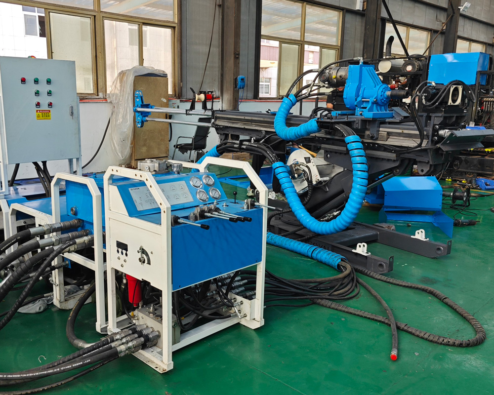
Tunnel Drilling Rig
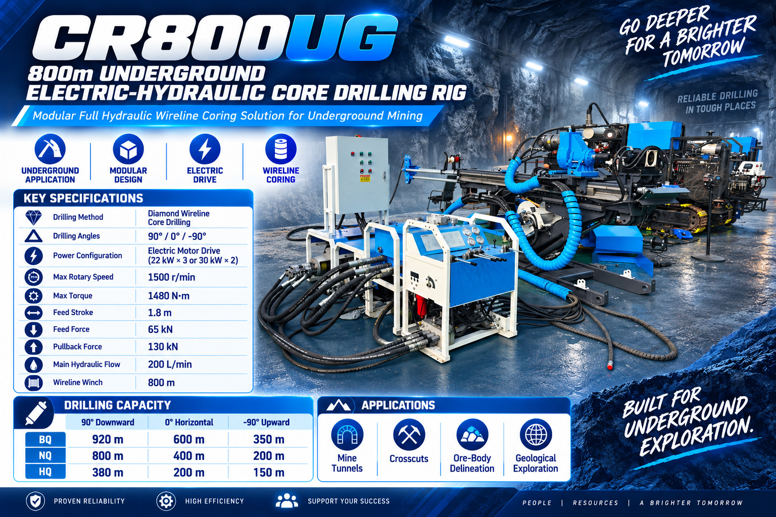
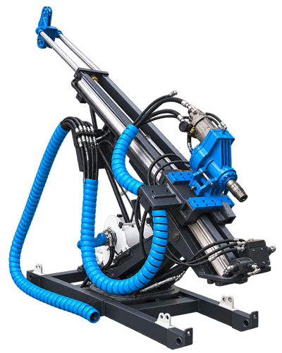
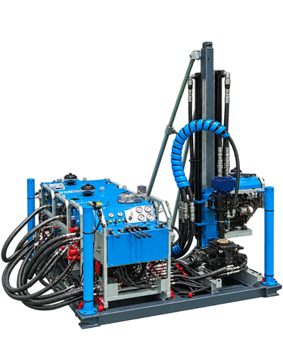
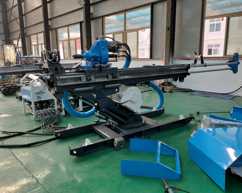
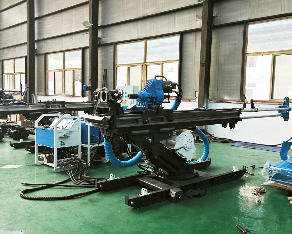
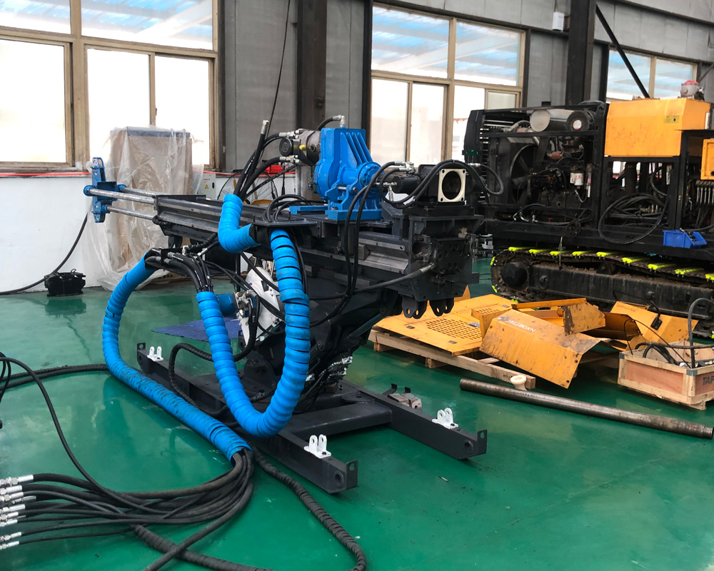
The CR800UG is an electric full-hydraulic core drill rig designed for underground mine tunnels, drill sites, and confined spaces. The equipment adopts a modular structure, allowing the power unit, feed mechanism, drill base frame, oil tank, and control unit to be transported separately and then assembled at the underground drill site. It is suitable for tunnels, crosscuts, drifts, and mining area drill sites where large surface drill rigs cannot directly enter.
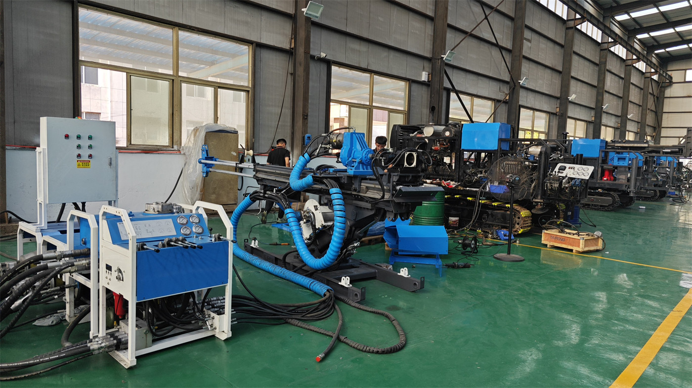
Underground mine spaces are limited by tunnel width, height, turning radius, and transportation methods. The equipment must not only have drilling capability but also accommodate transport and on-site layout. The CR800UG's split modules can be delivered to the working point in batches via inclined shafts, cages, mine cars, or tunnel transport systems, reducing space constraints caused by large complete machines entering the site.
The power system uses a 22 kW × 3 or 30 kW × 2 motor configuration, with a main system flow rate of 200 L/min and pressure of 210 bar. Compared to diesel power, electric motors do not produce combustion exhaust at the drill site, making them more suitable for underground mines with a stable power supply. The electrical scheme should be confirmed based on mine voltage, frequency, cable length, and starting method during actual configuration.
Under 90° reference conditions, the BQ reference drilling depth is 920 m, NQ is 800 m, and HQ is 380 m. This direction is suitable for verifying ore body extension, deep faults, surrounding rock changes, and potential replacement resources from the current mining level to deeper levels.
Under 0° reference conditions, the BQ reference drilling depth is 600 m, NQ is 400 m, and HQ is 200 m. Horizontal holes can be drilled directly from crosscuts or haulage tunnels to the side, used to determine ore body thickness, surrounding rock boundaries, fault displacement, and mineralization continuity, reducing a large number of ineffective hole sections drilled from the surface.
Under -90° reference conditions, the BQ reference drilling depth is 350 m, NQ is 200 m, and HQ is 150 m. Upward boreholes can be used to verify mineralization above tunnels, roof structures, resources in the upper part of mining areas, or targets that are difficult to control with downward holes. Different mines may have different definitions of angle sign conventions; the on-site installation direction and design drawings should be the basis before formal construction.
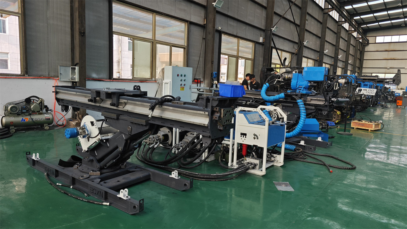
Vein gold deposits and structurally altered gold deposits require continuous confirmation of vein strike, dip, thickness, and grade changes during mining. The CR800UG can use existing tunnels to arrange multi-directional boreholes, determining ore body boundaries and internal structures through continuous core samples, providing geological basis for stope design, pillar control, and subsequent excavation.
Underground copper, lead-zinc, and polymetallic mines often require continuous supplementary drilling around production levels to verify ore body boundaries, fault locations, and new mineralization extensions. Underground boreholes are closer to the target body, allowing more concentrated acquisition of local ore section core data, which is beneficial for short-cycle updates to geological models.
The equipment can also be used for advanced geological surveys ahead of tunnel excavation, identifying faults, fracture zones, weak interlayers, and water-bearing structures through core sampling. For areas that may have water inrush, surrounding rock instability, or sudden lithology changes, obtaining core information in advance can provide a basis for support, drainage, and pre-grouting plans.
Water-bearing fractures and water-conducting structures underground directly affect mine construction safety. Through drill core, return water, and pump pressure changes, the development of fractures and water-bearing structures can be assessed. The equipment can be optionally equipped with a 120-series high-pressure plunger pump, with a maximum flow rate of 120 L/min and maximum pressure of 70 bar, for flushing and certain special circulation conditions.
The feed mechanism is driven by hydraulic cylinders with a stroke of 1800 mm, feed force of 65 kN, retraction force of 130 kN, and rapid traverse speed of 0.9 m/s. The drill string stress states for horizontal, downward, and upward holes are not the same; feed and retraction parameters should be adjusted based on hole direction, depth, and friction changes.
The power head uses a hydraulic top drive with a speed range of 0–1500 rpm and torque range of 600–1480 N·m, equipped with a 107 variable displacement motor. The wide speed range facilitates selecting working conditions based on BQ, NQ, HQ specifications and rock hardness, allowing parameter adjustments between intact hard rock and fractured hole sections.
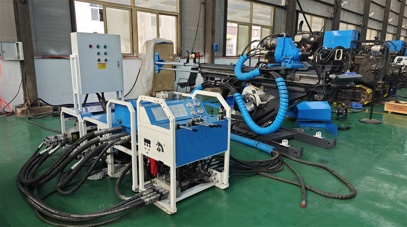
The drill rod clamp has a maximum applicable drill rod size of 108 mm, through-hole of 128 mm, and clamping force of 80 kN. Underground drill sites have limited space, and drill rod make-up/break-out and wellhead operations are concentrated; stable clamping can reduce the risk of drill rod slippage. During operation, the wear of clamping blocks and hydraulic pressure should be regularly checked.
The winch system has a rope capacity of 800 m using 6 mm wire rope. The data indicates a minimum lifting force of 800 N at full drum, maximum lifting force of 1800 N at empty drum, and lifting speeds from 1.8 m/s to 4.8 m/s. Wireline core drilling reduces repeated tripping of the entire drill string, which is beneficial for reducing auxiliary time in underground medium-deep hole operations.
The main system flow rate is 200 L/min with a pressure of 210 bar, and the auxiliary pump flow rate is 10 L/min with a maximum pressure of 150 bar. Underground environments have significant humidity, dust, and temperature variations; the cleanliness of hydraulic oil, high-pressure hoses, fittings, and filter status should be continuously checked to prevent contamination and leakage from affecting equipment reliability.
The hydraulic oil tank has a capacity of 100 L and uses water cooling. Underground air circulation is limited, and water cooling helps control hydraulic oil temperature, but cooling water supply and heat exchanger cleanliness must be ensured. If water quality is poor, the heat exchanger should be cleaned regularly to avoid scaling that reduces heat dissipation efficiency.
The reference weights of main modules include: power unit 240/270 kg, main feed mechanism 130 kg, drill base frame 120 kg, oil tank unit 120 kg, and control unit 90 kg. Before actual transport, a handling plan should be developed based on cage dimensions, tunnel gradient, track conditions, and on-site lifting capacity.
When encountering fault gouge, breccia, or strong fracture zones, the drilling run length should be shortened, feed force reduced, and return water changes observed. If necessary, casing should be used, flushing fluid adjusted, or segmented treatment performed. The focus in such formations is maintaining hole wall stability and improving effective core recovery, rather than simply pursuing footage.
Before equipment installation, the roof, sides, and floor support of the drill site should be checked; the drill base frame must be reliably fixed to avoid equipment displacement due to drilling reaction forces; cables and hydraulic hoses should be routed away from transport paths and sharp rock walls; when performing upward and horizontal holes, special attention should be paid to safety risks from drill rods, core barrels, and high-pressure fluids.
Standard motor configurations cannot be directly considered explosion-proof. In coal mines, gas mines, or underground environments with combustible dust, motors, electrical control boxes, cables, and protection systems with appropriate explosion-proof ratings should be selected according to local mine safety regulations. They must not be used directly in areas requiring explosion-proof protection without confirmation.
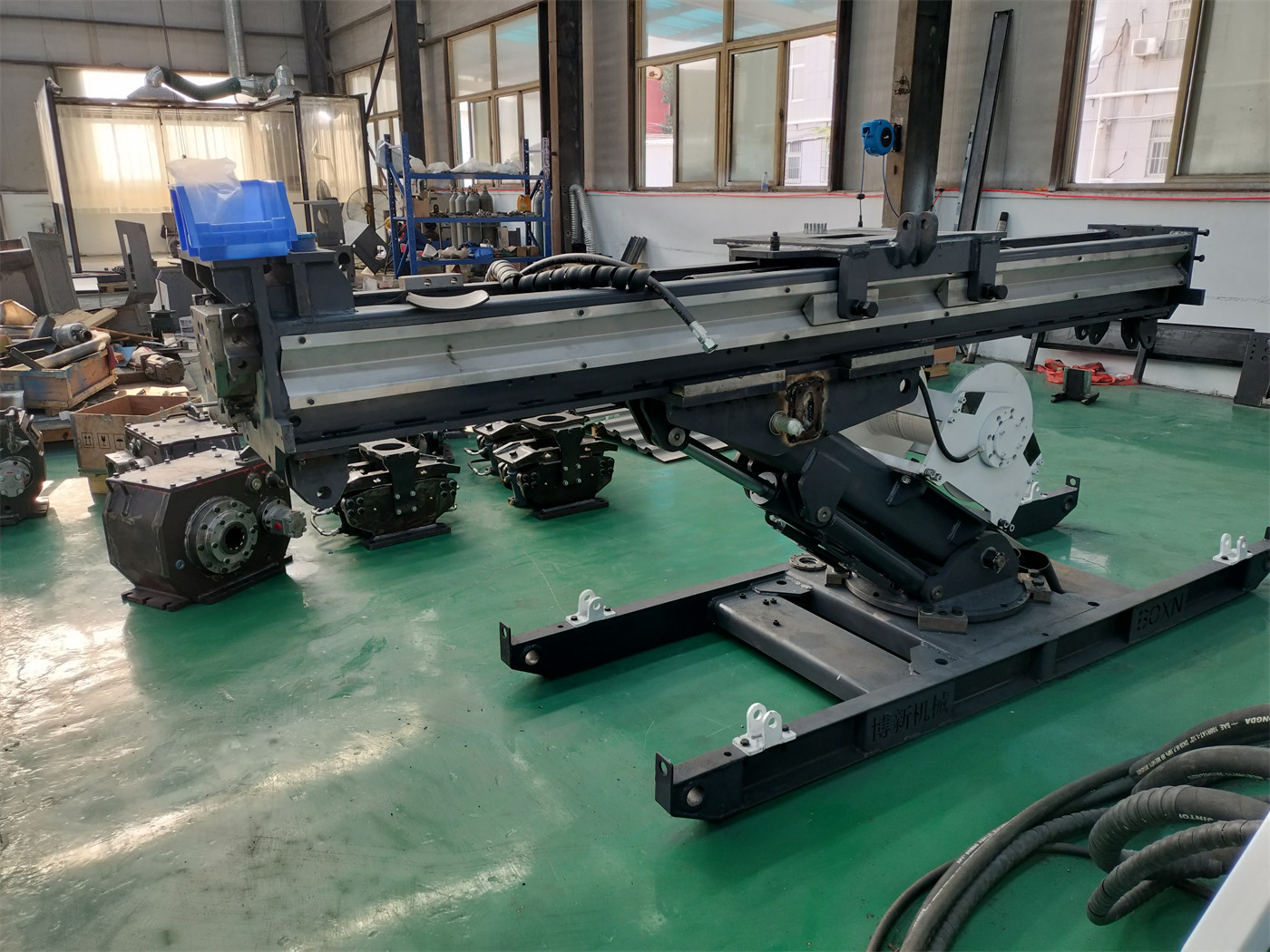
In the original parameters, the "control unit weight" has two different annotations: 130 kg in the control unit table, and 90 kg in the main module weight summary. This article retains the original annotations in the parameter tables; the final supply configuration and actual weight should be based on formal technical confirmation documents.
Due to differences in actual geological conditions, downhole tools, drilling angles, and operating methods, the final drilling efficiency, depth, and core recovery results should be based on on-site conditions.
| Parameter Item | Parameter Value |
|---|---|
| Reference Coring Capability by Drilling Direction | |
| BQ (90°) | 920 m |
| NQ (90°) | 800 m |
| HQ (90°) | 380 m |
| BQ (0°) | 600 m |
| NQ (0°) | 400 m |
| HQ (0°) | 200 m |
| BQ (-90°) | 350 m |
| NQ (-90°) | 200 m |
| HQ (-90°) | 150 m |
| Power System (Electric Motor) | |
| Motor Power | 22 kW × 3 / 30 kW × 2 |
| System Flow Rate | 200 L/min |
| System Pressure | 210 bar |
| Auxiliary Pump Flow Rate | 10 L/min |
| Auxiliary Pump Max Pressure | 150 bar |
| Power Unit Single Module Weight | 240 / 270 kg |
| Feed Mechanism | |
| Top Drive Stroke | 1800 mm, hydraulic cylinder feed |
| Feed Length | 1800 mm |
| Feed Beam Length | 2800 mm |
| Extension Mast Length | 2000 mm |
| Feed Thrust | 65 kN |
| Feed Pull | 130 kN |
| Rapid Traverse Speed | 0.9 m/s |
| Rotary Power Head | |
| Power Head Type | Hydraulic top drive |
| Speed | 0–1500 rpm |
| Power Head Torque | 600–1480 N·m |
| Hydraulic Motor | 107 variable displacement motor |
| Drill Rod Clamp | |
| Max Drill Rod Size | 108 mm |
| Through-Hole | 128 mm |
| Clamping Force | 80 kN |
| Hydraulic Oil Tank | |
| Capacity | 100 L |
| Weight | Empty 45 kg / Full 120 kg |
| Cooling Type | Water-cooled |
| Wireline Winch | |
| Rope Capacity | 800 m, 6 mm wire rope |
| Min Lifting Force | 800 N (full drum) |
| Max Lifting Force | 1800 N (empty drum) |
| Min Lifting Speed | 1.8 m/s (empty drum) |
| Max Lifting Speed | 4.8 m/s (full drum) |
| Control Unit | |
| Hydraulic Control Type | Hydraulic system |
| Electrical Control Type | Integrated electrical system |
| Operation Type | Hydraulic levers + electrical buttons |
| Documented Weight | 130 kg |
| Mud Flushing System (Optional) | |
| Model | 120 high-pressure plunger pump |
| Max Flow Rate | 120 L/min |
| Max Pressure | 70 bar |
| Main Module Weights (Reference) | |
| Power Unit | 240 / 270 kg |
| Main Feed Mechanism | 130 kg |
| Drill Base Frame | 120 kg |
| Oil Tank Unit | 120 kg |
| Control Unit | 90 kg |
We are a professional drilling equipment manufacturer specializing in the research and development, production and supply of water well drilling rigs, core drilling rigs, reverse circulation drilling rigs, down-the-hole drilling rigs, truck-mounted drilling rigs and mineral exploration equipment.
© 2026 Shandong Hengjianhang Construction Machinery Co., Ltd. All rights reserved.